EtherCAT Master
Contents
Introduction
In the context of the I-MECH project, funded by the European Commission under the ECSEL programme, we have ported the SOEM EtherCAT library on ERIKA.
This page explains how to setup and run the provided demo.
Requirements
For running the demo, an x86-64 platform with the following characteristics is needed:
- Supporting hardware-assisted virtualization (i.e. VT-x, VT-D, EPT) and capable of running the Xen hypervisor in HVM mode.
- With an Intel i210 network interface.
Demo
The provided demo assumes the Intel i210 network interface to be connected to a Beckhoff EL2004 EtherCAT slave. The demo has been tested on Advantech ARK-3520P-U7A1E.
To run the provided EtherCAT master demo, follow the next steps:
- Download the SOEM EtherCAT master stack from https://github.com/OpenEtherCATsociety/SOEM
- Download the bare-metal x86 toolchain available at this link http://erika-enterprise.com/download/erika3_x86_64_xtools.tar.gz and extract the downloaded archive on a local directory
- (optional) Put the directory containing the toolchain binaries in the
PATHenvironment variable before running RT-Druid. - Run the RT-Druid tool
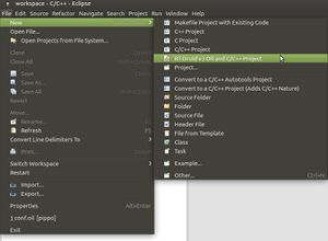
- Create a new project by clicking on
New→RT-Druid v3 Oil and C/C++ Projectas shown in the next Figure: - Name the new project (e.g.,
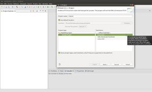
mytest) and select the Cross-GCC as shown in the next Figure: - Check the box for using an existing template and select
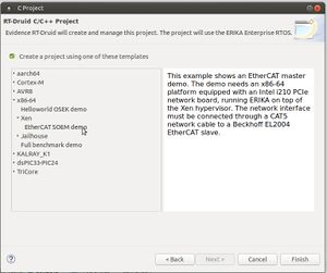
x86-64→Xen→EtherCAT SOEM demoas shown in the next Figure: - Right click the project and select
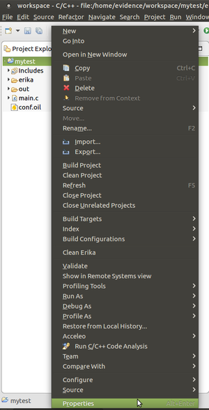
Propertiesas shown in the following Figure: - Click
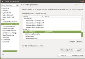
Oil→Generator properties, enable project specific settings and specify the directory containing the SOEM library for ERIKA3: - If you didn't put the toolchain in the
PATHdirectory, also set theGNU Compiler prefixproperty to/full/path/x-tools/x86_64-unknown-elf/bin/x86_64-unknown-elf-. - Edit the
main.cfile and set theSLAVE_NBvariable for the Bechkhoff EL2004 slave (note that the SOEM library numbers slaves starting from1). - Follow the instructions at this page for building and running the Xen iso image.
Motion control of CiA 402 compliant devices
CiA® 402 refers to CAN in Automation (CiA) CANopen® Drives and Motion Control Profile 402, which standardizes the functional behavior of controllers for servo drives, frequency inverters, and stepper motors.
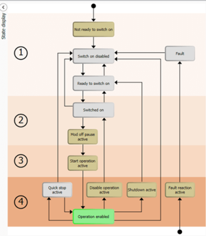
The profile describes the Finite State Automation (FSA) of the device, where each state specifies the internal/external behavior and the accepted commands:
The generic CanOpen specification for the automation provides an Object Dictionary, a grouping of objects accessible via the network in an ordered pre-defined fashion. Each object within the dictionary is addressed using a 16-bit index.
The CiA 402 extends the basic dictionary with specific objects and among these we can find Controlword and Statusword.
The Controlword is used to set the required states in the state machine. Object ID is 0x6040 and bits are defined as follows:
| Bit | Name | Abbreviation |
|---|---|---|
| 0 | Switch On | SO |
| 1 | Enable Voltage | EV |
| 2 | Quick Stop | QS |
| 3 | Enable Operation | EO |
| 4-6 | Operation mode specific | OMS |
| 7 | Fault Reset | F |
| 8 | Halt | H |
| 9 | Operation Mode Specific | OMS |
| 10 | Reserved | R |
| 11-15 | Manufacturer specific | MS |
The following bits are required when transitioning between states:
| Transition | Value (h) | BITS | |||||||
|---|---|---|---|---|---|---|---|---|---|
| 0 (SO) | 1 (EV) | 2 (QS) | 3 (EO) | 4-6 (OMS) | 7 (F) | 8-15 | |||
| 15 | Fault → Ready to switch on | 0x86 | 0 | 1 | 1 | 0 | xxx | 1 | xxxxxxxx |
8/9/0 | Non fault → Ready to switch on | 0x06 | 0 | 1 | 1 | 0 | xxx | 0 | xxxxxxxx |
| 3/5 | → Switched on(1) | 0x07 | 1 | 1 | 1 | 0 | xxx | 0 | xxxxxxxx |
| 4/4a | → Operation enabled | 0x0F/0x1F | 1 | 1 | 1 | 1 | xxx | 0 | xxxxxxxx |
(1) The switched on state is often bypassed by the master
The Statusword provides information about the operational status of the drive and is sent from the slave to the master. Object ID is 0x6041 and defined bits are:
| Bit | Name | Abbreviation |
|---|---|---|
| 0 | Ready to Switch On | RTSO |
| 1 | Switched On | SO |
| 2 | Operation Enable | OE |
| 3 | Fault | F |
| 4 | Voltage Enabled | VE |
| 5 | Quick Stop | QS |
| 6 | Switch On Disabled | SOD |
| 7 | Warning | W |
| 8 | Manufacturer Specific | MA |
| 9 | Remote | RM |
| 10 | Target Reached | TR |
| 11 | Internal Limit Active | ILA |
| 12-13 | Operation Mode Specific | OMS |
| 14-15 | Manifacturer Specific | MS |
The following table outlines the Statusword bits and the represented state:
| State | Statusword Bits | Functional Meaning |
|---|---|---|
| Not ready to switch on | xxxx xxxx x0xx 0000 | No CiA mode of operation selected |
| Switch on disabled(1) | xxxx xxxx x100 0000 | No motor torque - drive disabled |
| Ready to switch on | xxxx xxxx x01x 0001 | No motor torque - drive disabled |
| Switched on | xxxx xxxx x01x 0011 | No motor toque - drive disabled |
| Operation Enabled | xxxx xxxx x01x 0111 | Motor has torque - drive enabled |
| Fault reaction active(1) | xxxx xxxx x0xx 1111 | Motor is losing torque - drive disabling |
| Fault | xxxx xxxx x0xx 1000 | No motor torque - drive disabled |
| Quick stop active(2) | xxxx xxxx x00x 0111 | Not implemented |
(1) these states are automatically transitioned through
(2) quick stop active is not currently implemented
Controlling a CiA 402 drive with Erika + SOEM
Using the SOEM EtherCat library, Erika can control the position of a digital servo motor. Before executing Erika, it is useful to discover the mapping of the fundamentals SDOs (Controlword, Statusword, Current Position and Target Position) into the PDO in order to access them as simple memory in the IOmap provided by the SOEM stack. The latter provides the "slaveinfo" utility which prints the mapping of SDOs into the PDOs. The application must be executed on linux with the -map arguments
sudo ./slaveinfo <eth_interface> -map
This will print the mapping of SDOs into PDOs. A possible mapping could be the following:
 PDO mapping according to CoE :
 SM2 outputs
    addr b   index: sub bitl data_type    name
 [0x0000.0] 0x607A:0x00 0x20 INTEGER32    Target position
 [0x0004.0] 0x60FE:0x01 0x20 UNSIGNED32   Physical outputs
 [0x0008.0] 0x6040:0x00 0x10 UNSIGNED16   Controlword
 SM3 inputs
    addr b   index: sub bitl data_type    name
 [0x000A.0] 0x6064:0x00 0x20 INTEGER32    Position actual value
 [0x000E.0] 0x60FD:0x00 0x20 UNSIGNED32   Digital inputs
 [0x0012.0] 0x6041:0x00 0x10 UNSIGNED16   Statusword
These fields can be easily accessed using the function set_output_int16 and get_input_int16 implemente in the file oshw/erika/oshw.c:
 void set_output_int16 (uint16_t slave_nb, uint8_t module_index, int16_t value)
 {
  	uint8_t *data_ptr;

  	data_ptr = ec_slave[slave_nb].outputs;
  	/* Move pointer to correct module index*/
  	data_ptr += module_index * 2;
  	/* Read value byte by byte since all targets can't handle misaligned
     	   addresses */
  	*data_ptr++ = (value >> 0) & 0xFF;
  	*data_ptr++ = (value >> 8) & 0xFF;
 }
 void get_input_int16(uint16_t slave_nb, uint8_t module_index, int16_t *value)
 {
       uint8_t *data_ptr;

       data_ptr = ec_slave[slave_nb].inputs;
  	/* Move pointer to correct module index*/
  	data_ptr += module_index * 2;
       /* Read value byte by byte since all targets can't handle misaligned
     	   addresses */
       *value |= ((*data_ptr++) & 0xFF);
       *value |= ((*data_ptr) << 8) & 0xff00;
 }
After collecting such preliminary infos, the motor can be controlled following these steps:
- Bring the slave in OP state: After performing the NIC i210 init functions, Distributed Clock setup and PDO mapping, the SOEM stack shall let the slave reach the OPERATIONAL state as required by CiA402.
- Read the Statusword: at the beginning of the control loop, after the transmission/reception of the periodic PDO, Erika shall read the Statusword in order to acquire the current state of the drive. The function get_input_int16 can be used:
- CiA402 FSA implementation: after the acquisition of the Statusword, Erika shall set the drive into the Operation Enable state. According to the specification, a simple FSA implementation could be the following:
- Writing the Controlword: after setting properly the Controlword, it can be written using:
- Getting Current position and setting Target position : in the Operation Enable state, PDOs' mapping can be used to get the current position of the drive and then set the target position:
  ec_config_map(&IOmap); /*map slave's PDO into IOmap.inputs and IOmap.outputs */
  ec_configdc(); /* Configure the Distributed Clock */

  set_operational(); /* CiA402 requires OP state */
  print_slave_info();
After the initialization functions, Erika will enter in an endless control loop.
   #define SLAVE_NB (1)

   int16_t statusword = 0;
   /* The input address for get_input_int16 must be devided by two. 0xA
    is the starting address of inputs*/
   get_input_int16(SLAVE_NB, (0x12 - 0xA) >> 1, (int16_t*)&statusword);
  #define STATUS_WORD_MASK(x)          (x &= 0x6F)
  #define MODES_OF_OPERATION_INDEX	(0x6060)

  typedef enum{
       control_switch_on = 0,
       control_enable_voltage = 1,
       control_quick_stop = 2,
       control_enable_operation = 3,
       control_fault_reset = 7,
       control_4 = 4,
       control_5 = 5,
       control_6 = 6,
       control_8 = 8
   }control_bit_t;

  typedef enum{
       /*xxxx xxxx x0xx 0000*/ Not_ready_to_switch_on = 0x0,
       /*xxxx xxxx x1xx 0000*/ Switch_on_disabled = 1 << 6,
       /*xxxx xxxx x01x 0001*/ Ready_to_switch_on = (1 << 5) | 1,
       /*xxxx xxxx x01x 0011*/ Switch_on = (1 << 5) | 3,
       /*xxxx xxxx x01x 0111*/ Operation_enabled = (1 << 5) | 7,
       /*xxxx xxxx x00x 0111*/ Quick_stop_active = 0x7,
       /*xxxx xxxx x0xx 1111*/ Fault_reaction_active = 0x0f,
       /*xxxx xxxx x0xx 1000*/ Fault = 1 << 3
       }statusword_state_t;

       STATUS_WORD_MASK(statusword);

       switch(statusword){
       case (Not_ready_to_switch_on): {
     		/* Now the FSM should automatically go to Switch_on_disabled*/
                       break;
               }
               case (Switch_on_disabled): {
                        /* Automatic transition (2)*/
                       controlword = 0;
                       controlword |= (1 << control_enable_voltage)
                       				| (1 << control_quick_stop);
                       break;
               }
               case (Ready_to_switch_on): {
                       /* Switch on command for transition (3) */
                       controlword |= 1 << control_switch_on;
                       break;
               }
               case (Switch_on): {
                       /* Enable operation command for transition (4) */
                       controlword |= 1 << control_enable_operation;
                       break;
               }
               case (Operation_enabled): {
                       /* Setting modes of operation
                               * Value Description
                               -128...-2 Reserved
                               -1 No mode
                               0 Reserved
                               1 Profile position mode
                               2 Velocity (not supported)
                               3 Profiled velocity mode
                               4 Torque profiled mode
                               5 Reserved
                               6 Homing mode
                               7 Interpolated position mode
                               8 Cyclic Synchronous position
                               ...127 Reserved*/

                       uint16_t mode = 8; /* Setting Cyclic Synchronous position */
                       int mode_size = sizeof(mode);
                       SDO_result = ec_SDOwrite(SLAVE_NB, MODES_OF_OPERATION_INDEX, 0,
                                                0, mode_size, &mode, EC_TIMEOUTRXM);
                       break;
               }
               case (Quick_stop_active): {
                       break;
               }
               case (Fault_reaction_active): {
                       break;
               }
               case (Fault): {
                       /* Returning to Switch on Disabled */
                       controlword = (1 << control_fault_reset);
                       break;
               }
               default:{
                       OSEE_PRINT("Unrecognized status\n");
                       break;}
       }
Please note that in the Operation Enabled state, the Mode of Operation is selected through the 0x6060 SDO.
set_output_int16(SLAVE_NB, 8 >> 1, controlword);
 int16_t value_high = 0;
 int16_t value_low = 0;
 int32_t value = 0;
 /* Getting value */
 get_input_int16(SLAVE_NB, (0xA - 0xA) >> 1, (int16_t*) &value_low);
 get_input_int16(SLAVE_NB, (0xC - 0xA) >> 1, (int16_t*) &value_high);
 value = ((value_high << 16) & 0xffff0000) | (value_low & 0x00ffff);
 value += 400;

 /* Setting output */
 set_output_int16(SLAVE_NB, 0x0 >> 1, (int16_t)(value & 0xffff) );
 set_output_int16(SLAVE_NB, 0x2 >> 1, (int16_t)((value >> 16) & 0xffff));
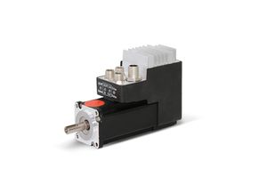
All the steps described above have been tested on the ELMO's Gold duet servo drive:
